5 Ways to Eliminate Ground Loops – Part I
A Brief Introduction
Most workers already know that proper ground- ing is a fundamental safety precaution for all kinds of electrical equipment. However, it’s less well known that while grounding can prevent and resolve many safety and power issues, improper grounding can create problems in data logging, data acquisition, and measurement and control systems.
One of the most common problems is known as ground loop feedback–an electrical phenomenon often resulting when different electrical circuits within a system and its peripherals have different connections or paths back to earth ground. Furthermore, this can also be a seasonal issue where problems come and go based on climatic conditions. The Applica- tion Specialists at CAS DataLoggers have put together this brief introduction on the subject.
Ground Loop Feedback Explained
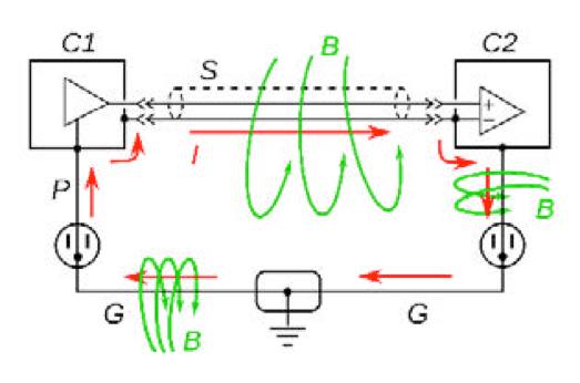
Ground loop feedback is a frequently encountered wiring issue arising when two or more connected electrical devices have more than one path to earth ground. Together, the sepa- rate paths form a loop. Electrical and magnetic fields which flow through the loop can gen- erate unintended currents and voltages. Or, the ground points of the different devices may not be at the same potential voltage due to current and resistance in the ground path. The net effect is that while it is believed that the devices have the same ground reference point, in fact, they don’t, and this difference can appear as a simple offset in measured values or as signal noise that corrupts the devices’ normal operation.
Whether using different safety grounds or a safety ground and an earth ground, one of the most common examples is buzzing/humming sounds caused by currents induced in ground loops from mains (60 Hz) AC power. In video applications, users will notice
this feedback in the form of onscreen stripes, while computer and networking users can experience shutdowns or gaps in their data communication. Engineers and technicians collecting data often find that their readings and data show offsets that may change over time or noise in the measured values. In a worst-case scenario, this could cause an interruption in operations since many businesses heavily rely on PLCs and measurement systems for process and machine control, quality control, final test, etc.–yet ground loops often escape troubleshooting investigations and are equally neglected as a factor in many installations, arising later when electrical configuration or environmental condi- tions change.
Computers, data loggers, and data acquisition/control systems are normally connected to the ground through their AC power supply and the ground pin on the plug that goes into the wall outlet that shares the ground wire in common building wiring. These devices may also be connected to each other by data communications cables. Ethernet cables are pretty good at maintaining ground isolation but serial communications cables, RS232 for example, have their own ground conductor. Now if the computer is plugged into an outlet in one area of the building and an RS232 device it is connected to is in a different area of the building it can create a multi-path connection and a ground loop.
Another example is a computer controlling a piece of manufacturing equipment. The computer is probably plugged into a standard 110VAC out but the manufacturing ma- chine may require 220 or 480VAC so it is fed from a different breaker panel than the PC. Each breaker panel can have its own local ground stakes. Ideally, these ground stakes are supposed to be no resistance on that ground wire and no voltage drop. However, we have seen cases where, for whatever reason, there is resistance in the path to local ground. It could be a bad connection on one of the ground wires or it could be that at certain times of the year, the area around the ground stake becomes very dry and there is some non-ze- ro resistance to true earth ground. The result is that the computer and the machine it is controlling don’t share the same true ground which can result in erratic operation or even complete shutdown.
Ground loops can also affect low-level measurements through the effect of cabling. Normally, for sensitive measurements, a shielded cable will be used where the purpose of the shield is to protect the signal from any electromagnetic interference in the envi- ronment. For correct operation, the shield should be connected to the ground only at one end, this way electrical interference in the environment will be collected by the shield and carried to the ground keeping the sensitive signal clean. However, if by mistake the shield is connected to the ground at both ends it will immediately create a potential ground loop. Now any electrical interference in the environment will create a current in the shield which will then be coupled directly to the signal being measured in the form of electrical noise.
Increasingly, ground loop feedback poses a threat to industrial processes given the sen- sitivity of newer electrical equipment. As an example, the more recent variable frequency AC drives can be controlled by an external analog voltage signal. These drives may have a sensitive input front end and when encountering noise on the control signal, the drives can experience errors or even failure.
In the upcoming part 2, find out how exactly to diagnose ground loop feedback as well as five steps to reduce and prevent ground loops from occurring.