Precision Clocks used in Software Defined Radios (SDRs)
Introduction
It is no secret that digital electronics dominates almost every aspect of modern technology, from logical computation to signal processing and radio frequency (RF) applications. In fact, most of the RF systems being developed today have already replaced most of the onboard analog functions with software-based elements, which provides much more flexibility, reconfigurability, and immunity to environmental conditions. The fundamental component of digital-based RF systems is the software-defined radio (SDR). SDRs are mostly based on digital electronics and therefore carries the burden of being completely dependent on a clock system to regulate timing, synchronicity, analog-to-digital conversion, and speed of digital functions. Robust clocking systems found on time boards in these SDRs are especially critical in multiple-input multiple-output (MIMO) applications, which have to deal with a huge amount of very fast data transmission. Oven-controlled crystal oscillators (OCXO) are the foundation of precise timing solutions, providing a very stable and accurate clock signal, using a temperature-controlled chamber to maintain the quartz temperature constant, thus preventing frequency drifts due to environmental conditions. In an SDR, the OCXO is responsible for defining the frequency of radio transmitters, base stations, test and measurement devices, and military applications with tremendous accuracy.
In this article, we discuss how OCXOs are applied in high-end SDRs, providing up to 10 MHz clock signals, and how this clock is distributed over the many components of the SDR, including phase-locked loops (PLL), analog to digital convertor/digital to analog convertor (ADC/DAC) JESD interfaces, frequency synthesizers, and the field programmable array (FPGA) in the digital domain. The OCXO signal can also be outputted for external synchronization with other instruments. We will discuss how the timing solutions are calibrated to ensure a known phase and deterministic behavior of the clock signal, improving the performance of the SDR. We will conclude with an overview about how the precision clock allows the many functionalities of SDR, including up/down-conversion, MIMO synchronicity, and frequency tuning mechanisms.
What is an SDR?
The term SDR refers to any RF device that has most of its signal processing and managing system based on software. The motivation for using SDRs instead of conventional analog radios is flexibility; the flexibility of moving functionality into the software domain enabling easier implementation of digital signal processing (DSP) functions in software-based systems, such as PCs and FPGAs when compared to customized hardware. This allows for a commercial-off-the-shelf (COTS) SDR to be utilized in a wide variety of applications because of the flexibility and reconfigurability of the digital board. SDRs come in different size, weight, and power (SWaP) configurations, ranging from small and portable low-power transceivers to immense high-power base stations.
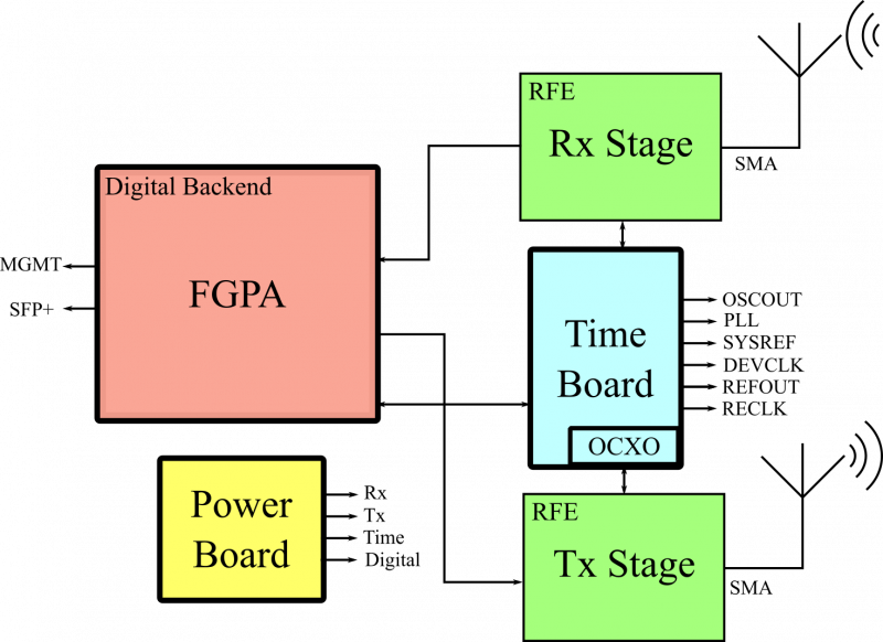
The basic architecture of an SDR consists of a radio front-end (RFE) and a digital backend (DBE). The RFE is responsible for both the receive (Rx) and transmit (Tx) functions, often providing more than one channel in MIMO SDRs. The channels operate with a very wide tuning range with very high bandwidths; the highest performance SDRs operate across a range from near DC to 18GHz with up to 3 GHz of instantaneous bandwidth and multiple channels, each one with a dedicated ADC/DAC interface. The digital backend consists of an FPGA, which reads the amplified and filtered received signals from the Rx RFE and can generate transmission signals to the Tx channels of the RFE. The inclusion of high-end FPGAs allow SDRs to perform DSP functions, including modulation, demodulation, up/down-converting, filtering, and data packetization on board.
Although the functional architecture of the SDR is divided between RFE and digital backend, the hardware itself is composed of five basic elements, commonly divided as separate circuit boards: the RFE Rx board, the RFE Tx board, the power board, the timing board, and the digital board. The RFE Rx and Tx boards are responsible for the analog processing operations, including amplification, filtering, mixing, and analog-to-digital or digital-to-analog conversion, terminating with SMA connections at the antenna. The digital board contains the FPGA with many interfaces, including optical links, such as qSFP+, for Ethernet communication to send and receive data from other digital equipment. Power is generated and distributed by the power board, which converts the input voltage (from the AC line or batteries) to voltage levels that are acceptable to each board. Finally, the timing board, which is the focus of our article, generates and distributes all timing signals, including the Tx and Rx clocks and the digital board clock.
To understand how important the clock is in an SDR, we need to take a closer look inside the RFE and the backend. Both the Tx and Rx boards of the RFE stage use mixers to upconvert and down-convert the signal, significantly facilitating the design of the filters. The core of the mixer is the local oscillator (LO), where the tuned frequency of the LO is defined by a signal generated by the timing board, so the frequency stability of both Rx and Tx up/down converting functions are completely dependent on the timing board stability. Furthermore, the whole digital backend needs a precision clock for proper operation, driving FPGA functions such as SERDES interface, CORDIC mixing, and Ethernet packaging. Finally, the timing board also provides the clock for external signals through SMA connectors, including PLL, OSC Out, SYSREF, and REFOUT.
What are OCXOs?
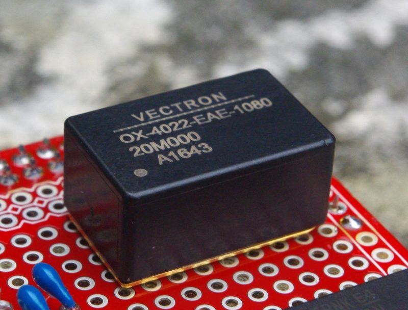
Oven Controlled Crystal Oscillators, or OCXOs, are crystal-based components capable of maintaining the quartz at a constant temperature, by heating the crystal inside the package in a closed-loop fashion. This approach is absolutely needed in applications that require a very high degree of frequency stability. Besides the crystal, the central part of the OCXO is the heating component, which typically requires a significant amount of power to operate. Both crystal and heater are enclosed in a package, which varies greatly with the manufacturer and specifications. The characteristics and performance of the OCXO are highly influenced by how the crystal is cut, with different trade-offs arising depending on the technique. The OCXOs used in Per Vices SDRs apply the stress compensated (SC) cut, which provides superior overall stability in terms of frequency, due to the thermal and mechanical robustness, and low phase noise.
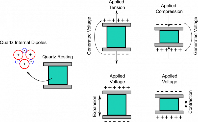
Like any other crystal-based device, the functionality of the OCXO relies on the piezoelectric effect of quartz. The OCXO is typically composed of a quartz crystal with electrodes coated on its surface. When a voltage is applied to the electrodes, the internal dipoles of the quartz are affected by the external voltage, which results in a deformation of the crystal in the direction of (or perpendicular to) the applied potential (Figure 3). Inside an electronic circuit, this piezoelectric crystal can act as a mechanical resonator, favoring a particular set of frequencies to be amplified, while rejecting the rest of the spectrum, allowing a single harmonic to be generated in the circuit. This harmonic depends on several characteristics of the crystal, including cut, material, and temperature.
In the context of SDRs, there are several important parameters that are crucial for the right selection of the OCXO. Here we discuss some of the most important ones:
– Operating Temperature Range: defines the range of temperatures that the OCXO can operate while yielding the performance levels described in the datasheet.
- Frequency Stability: given in parts per million (ppm), it describes how stable is the output frequency of the crystal, that is, how much the first harmonic can change during normal operation.
- Frequency Tolerance: it is the maximum error related to the central frequency that is allowed by the model. The more precise the application, the lower the tolerance.
- Aging: relates to the lifetime of the OCXO. The accuracy of the crystal drifts in time, due to the mechanical properties that define the resonance frequency.
- Phase Noise: phase noise is a random variation in the phase of the oscillating signal, and can generate serious jitter problems in the clock system. Ultra-low noise devices are required in highly deterministic operation.
OCXOs in SDRs
In SDR applications, it is crucial that the device is able to recover the received signal without problems. In this context, high-end SDRs require low phase noise and high-stability OCXOs to operate properly, which offers a central frequency of 10 MHz (with a range between 5 and 20 MHz typically), temperature stability of 5 parts per billion (ppb), noise floor of -175 dBc/Hz, and ± 50 ppb of tolerance. The aging drift is also important, as many SDRs are used in remote locations that prevent constant hardware replacement. Such high stability clocks also provide a ± 100 ppb of tolerance drift in the first year, and only ± 30 ppb over the following years of use, showing remarkable stability for long-term use.
One of the main applications of OCXOs is for SDR synchronization. Although very stable, OCXOs often need to be synchronized by a signal with higher accuracy, especially in satellite applications (GPS for instance), where a single pulse per second is used to discipline the OCXO in a master/slave configuration. Master/slave systems have two types of operation modes: the synchronized state and the “hold over” state, which occurs between synchronizations. By disciplining the OCXO, the REFOUT signal of the SDR can be used to externally synchronize other equipment, including vector network analyzers, test and measurements instruments, and base station synchronization.
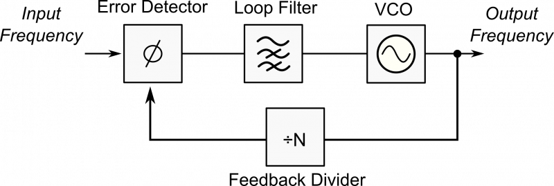
The reference clock generated by the OCXO has a significant impact on the Rx channel, and errors in this stage can be significantly amplified by the LO. In SDRs, the LO is typically implemented by a PLL, which can increment the clock frequency by several orders of magnitude using a feedback loop (see Figure 4). The higher frequency obtained by the PLL is then used in mixers for upconverting and down-converting, and the most important parameters in these modules are the phase noise, the spurious levels, and the lock time.
Moreover, PLLs are also responsible for generating the high-frequency clocks necessary to drive ADCs and DACs. In these cases, low jitter is mandatory for high-performance signal conversion. To drive multiple ADCs and DACs in a synchronous way, high-end SDRs implement the JESD204B interface, which requires the device clock and the SYSREF signal to be phase-locked with each other. This highlights the importance of a precision clock in MIMO operations, as synchronization cannot be guaranteed if the clock source lacks determinism and stability.
Conclusion
Precision clock generation is a fundamental part of high-performance SDRs that cannot be take for granted. The timing board is one of the five main printed circuit boards (PCBs) in many SDR systems, responsible for controlling the operating frequency, the speed of DSP functions, and the synchronicity of the channels. At the core of the timing board is the OCXO, which uses a feedback thermal loop to maintain the crystal at a constant speed. This feature allows the OCXO to provide a stable and reliable frequency to the whole SDR. There are several parameters that must be considered when selecting the right crystal for the SDR, including temperature range, frequency stability, aging, tolerance, and phase noise. OCXOs are applied in many parts of the SDR, generating the base clock for PLLs, mixers, JESD204 interfaces, and external triggers. Therefore, any high-end SDR relies on a high-performance clock system.
Contact
Per Vices has extensive experience in designing, developing, building, and integrating high-performance SDRs in many RF applications, including satellite communications, EW/SIGINT, medical, radar, low latency links, spectrum monitoring, test & measurement, and mobile communications. Contact solutions@pervices.com today to see how we can help you with your SDR needs.