Multiphase Synchronization: Controlling Conducted Noise in a Military-Grade DC-DC Switching Power Supply
Reducing noise generated on the input lines of DC-DC converters is necessary to meet stringent Electromagnetic Interference (EMI) standards in military applications. When connecting the input of DC-DC converters in parallel to the same bus, the task becomes more difficult. In this article, Christian Jonglas, technical support manager at GAIA Converter, discusses the issue and explains how the multiphase synchronization of a DC-DC switching power supply can result in significant reductions in noise levels.
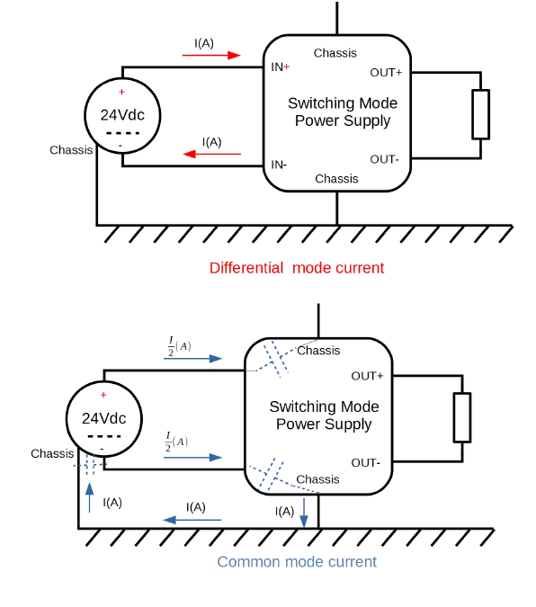
Switching Mode Power Supplies (SMPS) are preferred to linear types due to their efficiency and consequently their lightweight. However, across all of the possible conversion topologies, SMPSs generate differential mode (DM) and/or common-mode (CM) electrical noise on inputs and outputs, and electromagnetic radiation at some level, due to fast transitions of switching transistors and diodes.
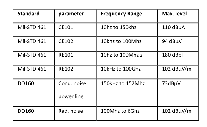
DM noise appears across the line and return connections and CM noise is from the line and return together to the ground (Figure 1). When there is a requirement to meet a specification for noise, whether conducted or radiated, it is advantageous to minimize DM first, as this is a source of radiation on leads and also factors into CM measurements. In addition, a standard Line Impedance Stabilisation Network (LISN), used for CM measurement, registers a combination of CM and DM signals. For military-grade DC-DC converters, the Electro Magnetic Compatibility (EMC) limits to be met are listed in Table 1.
Different Switching Topologies, Different Input Current Waveforms
The level of DM noise on the input of a DC-DC converter is measured as current with a specified series blocking inductor or voltage into 50 ohms, AC coupled onto the power lines. The amplitude varies with the switching topology and is generally highest for converters with ‘discontinuous’ input current such as ‘buck’ or isolated forward types.
Boost converters have continuous input current at higher power although they can be operated in a discontinuous mode at lower powers. In all cases, the current waveform into the switch combines a square and sawtooth or triangular waveform. A capacitor internal to the converter (at its input) levels out the waveform to approximate DC, sourced from the supply.
The maximum residual ripple and noise are what is set by the EMC standard limit lines. If the input current is decomposed into a square and sawtooth/triangle elements, their timing, and amplitudes, Fourier analysis can predict the spectrum of harmonics and their amplitudes. This analysis is key to developing an effective conducted emission filter design to apply attenuation as required. For example, with a triangle current waveform typical of a flyback converter in discontinuous mode, the current I sin(n), the amplitude of the sine wave representing the nth harmonic of the current waveform into the switch is:
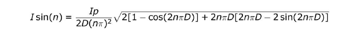
Where Ip is the peak current of the sawtooth and D is the duty cycle.
The DC-DC input capacitor forms a single-pole filter, an extra preceding inductor forms a double pole filter and a further upstream capacitor forms a three-pole Pi-filter, with -20dB, – 40dB, and -60dB respectively per decade attenuation with frequency. The attenuation can then be evaluated at the harmonic frequencies to ensure that the current I sin(n) is reduced sufficiently with the minimum level of filtering.
The conducted emission filter design must also meet the ‘Middlebrook criteria’ [1] for stability; the output impedance of the filter must be lower than the input impedance of the DC-DC converter at the filter self-resonant frequency. The filter must anyway be rated for the DC current passed with a good margin before saturation and damped to avoid ringing and possible overvoltage and ‘peaking’ of noise. Damping is either achieved with an additional RC network or the filter capacitors are chosen to have high enough ESR to have the same effect. As a ‘rule of thumb,’ CD should be >5 x CIN and a starting point for RD is SQRT(L/CIN)
Connecting DC-DC Converters in Parallel
When connecting DC-DC converters in parallel, the differential noise produced becomes harder to predict. If the converters are nominally operating at the same frequency, the current noise at the fundamental switching frequency I is given by:
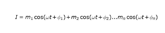
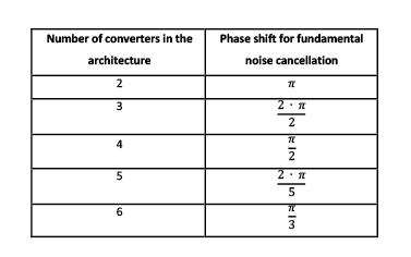
Where mn is the amplitude of converter n and ɸn is the phase difference in switching between converter n and converter 1. In the simple case of all amplitudes being equal at value M, the total noise I can vary from 0 to nM, corresponding to random phase differences causing full cancellation or addition when the phase is 0° or multiples of 360°. To ensure cancellation, synchronization can be applied so that the fundamental repetition rate of each converter is identical, with each separated in phase such that the noise current from the fundamental is canceled. This is implemented by a phase delay between each converter cycle start point, of 2π/n. The phase shift required is shown for up to six converters in Table 2.
Number of converters in the architecture Phase shift for fundamental noise cancellation
How to Achieve 20dB Attenuation
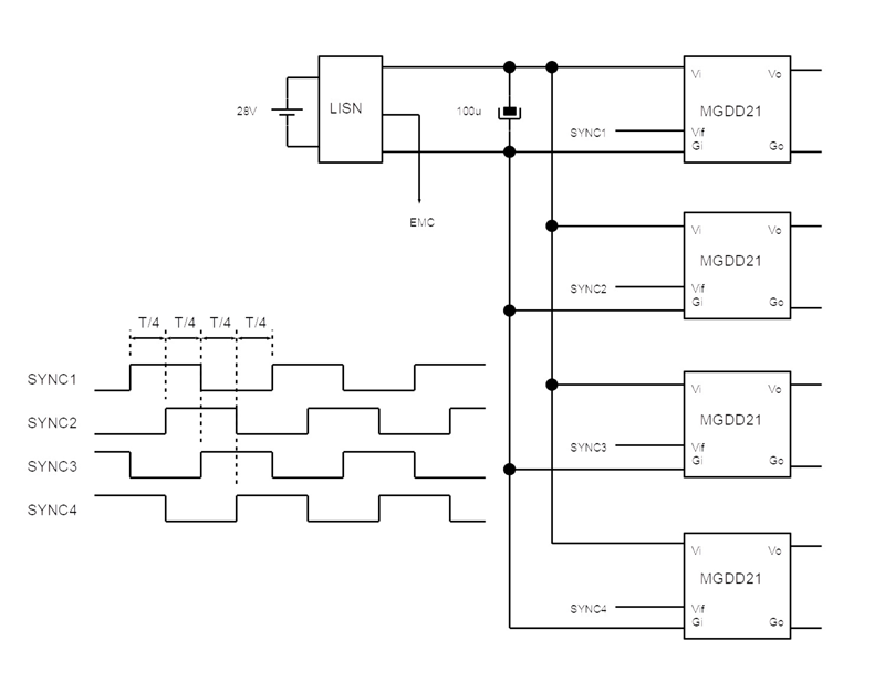
For two converters, a phase shift of 180° or π radians is equivalent to an inverted synchronization signal and is easy to implement logically. Other phase shifts might be most easily generated in a microcontroller or simple logic network. The waveforms for four converters are shown in Figure 2. A resulting EMI plot of four converters synchronized this way and loaded at 80W total is shown in Figure 3, with the fundamental attenuated compared with no synchronization. Full cancellation does not occur due to tolerances and the small differences in loading between the converters.
An additional benefit of the phased synchronization technique is reduced stress on input capacitors due to the lower ripple current. This aids reliability and boosts efficiency by reducing losses in the input capacitor’s Equivalent Series Resistance (ESR).
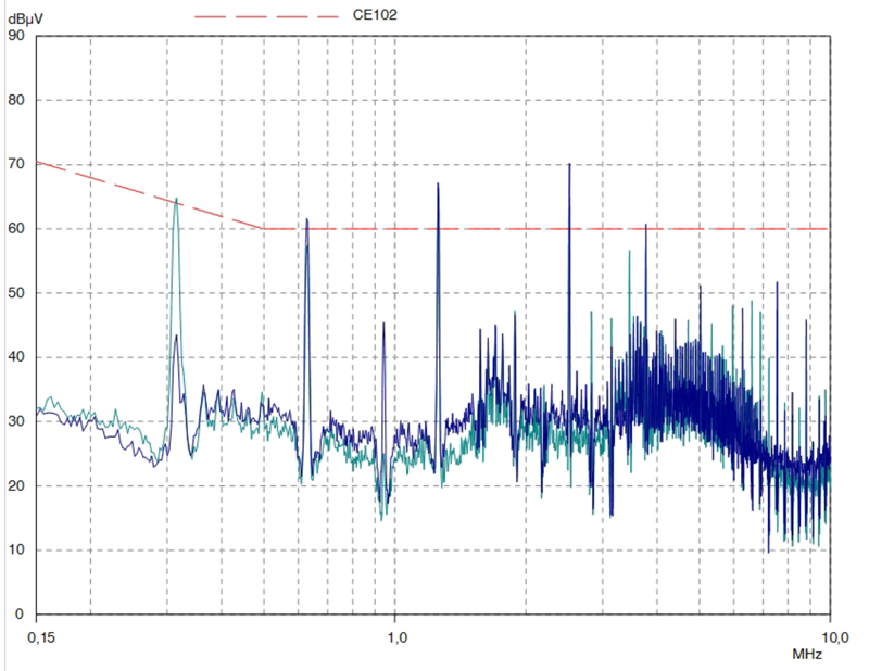
In this example, the fundamental noise at 300kHz is reduced below the CE102 limit line by over 20dB with no extra filtering. Harmonics, however, are still high and in fact, some will add with phased synchronization. This is because, for example, with a π/2 fundamental phase shift, this is equivalent to shifting the fourth harmonic by 2π or a complete cycle, causing the addition of signals. At higher harmonics, the tolerance of the phase shift also has a larger effect on cancellation. However, filtering harmonics is relatively easy as L and C values each can reduce by a factor of 4 for the fourth harmonic, compared with the fundamental, for the same attenuation.
Real-World Figures Demonstrate Noise Attenuation
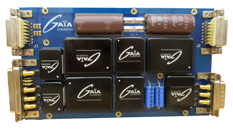
As a real-life demonstrator of the effectiveness of the phased synchronization technique, GAIA Converter designed a board with six of their DC-DC converters, one front end one filter in different configurations providing single and bi-polar outputs from a nominal 24 /28Vdc input at a total of 120W (Figure 4).
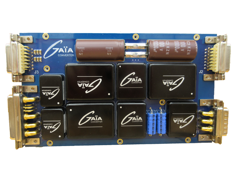
The board includes the logic to perform 180° (π) synchronization of two separate groups of converters as well as the ability to synchronize and phase four converters at π/2. The DC-DC converters include isolated and non-isolated types including the MPSGS14ED, a military-grade Point of Load converter that features fast output tracking, a constant current function, and wide -36% to +700% voltage trimming.
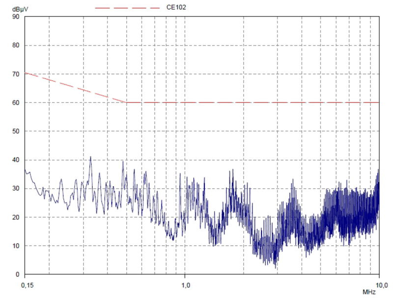
The board also includes GAIA Converter’s LHUG150N ‘Active Input Bus Conditioner’ which provides +/-100V transient protection, reverse polarity protection, power and inrush limiting, and a novel 50ms to 200ms holdup function utilizing a small capacitor whose voltage is boosted up to 60V irrespective of input voltage and is switched-in to the input when an interruption occurs. The board complies with military and avionic standards MIL-STD-704, DO160, MIL-STD-461, and MIL-STD-1275 and meets CE102 emissions limits with a margin of better than 20dB (Figure 5). This is achieved with the phased synchronization function along with a low-profile EMC filter type FGDS-12-100 which is just a 1″ x 1.2″ footprint, occupying only 5% of the board area.
Conclusion
When paralleling DC-DC converter inputs, synchronization is a valuable tool to make EMI signatures consistent so that analytical methods may be used to design filters for EMI standards compliance. Additionally, the phasing of synchronization signals appropriately can result in the cancellation of noise currents, particularly at the fundamental frequency, which can be the hardest to filter. The result can be a dramatic reduction in the size, weight, and cost of EMI filter networks.
References
[1] R. D. Middlebrook, “Input filter considerations in design and application of switching regulators” in Proc. IEEE IAS Annual Meeting 1976, pp. 366-382.